|
|
||
|
****JavaScript based drop down DHTML menu generated by NavStudio. (OpenCube Inc. - http://www.opencube.com)****
|
||
|
|
||
|
****JavaScript based drop down DHTML menu generated by NavStudio. (OpenCube Inc. - http://www.opencube.com)****
|
||
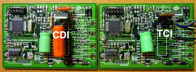
Programmable Digital Ignition CDI / TCI
NEW! Assembled ignition/EFI kit. It includes a powerful PIC18F6627 microcontroller at 40 mhz, and it is provided with the IGNITION firmware loaded (EFI firmware is optional)
more info: info@sportdevices.comIndex
- Differences between CDI and TCI
- Programmable CDI (Capacitive Discharge Ignition)
- Programmable TCI (Transistorised Coil Ignition)
- Ignition test machine
- Download files
- Other Links
Differences between CDI and TCI
CDI
TCI
- CDI is fired by using a charged capacitor (typical voltages 300-600 v, typical capacity: 1-4 uf
- Delay time is applied directly after the pickup pulse to fix the spark position
- CDI spark is shorter and more powerful than TCI spark
- CDI is more suitable to work at high rpm
- CDI needs an inverter to increase voltage upto 300 or 400 volt if used with 12 volt battery
- TCI is fired charging the coil itself before fire the spark. Time taken to charge the coil is called dwell time. The spark is made when the current across the coil stops, and the coil collapsates and fires the spark
- Delay time is applied after the pickup pulse but dwell time has to be substract from the total time, to fix the spark position
- TCI uses a simpler design and doesn't need capacitors
Programmable CDI (Capacitive Discharge Ignition)
The next schematic shows the coil configuration at magnetic plate and the position of the pick-up at the outer sider of the plate. This pick-up is triggered by the step on the plate. Below are shown the signals measured by means of an oscilloscope at the output of the magetic plate, and the output of CDI for the primary of the HV coil.
Ignition performing
The ignition explained here is a conventional one in which the trigger is controller by means of a microcontroller, in this case PIC16F84 of MicroChip. This micro has a FLASH memory that can be written with a simple programer that you can build easily, all information about the programmer can be found at JDM.
PIC receives the signal from the pick-up and delays it by using an internal table. This means that the starting point of the ignition should be place before of PMS at the most advanced point in which you want to the ignition works.
First graph shows the real advance curve measured in degrees over the PMS, nevertheless the PIC can not perform advancing, else it will make a delay from the pickup signal (typically at 36 degrees). For the maximum advance point, the PIC will do a zero delay (for 36 deg. advance). When this maximum value is determined, the second graph can be done, this graph shows delay in degrees that the PIC should perform after receiving the pickup pulse.
The PIC computes the elpased time between the last pulse and the present one, and by using this count it access to a table in which are stored time to delays vs measured period.
CDI Schematic (PIC16F84)
NOTES about the circuit:
- Schematic is designed to enable starting whithout battery.
- It is assumed that the pickup generates a double pulse.
- the first pulse (the negative one) is catched with the transistor to be processed by the PIC.
- The second pulse (the positive one) is sent directly to the SCR (thyristor) to enable starting when the PIC has not current yet.
- At least a 24 degree delay is required from the first pulse to the second to enable this configuration to work.
- If this delay can not be reached, it is recommended to remove the direct diode (into the gray box) or to use two pickups, one at 12 degrees and the other at 36 degrees (o higher).
- these values are typical values, some engines can run upto 42 degrees of advance.
- The circuit inside the gray box is provided in order to enable the engine to start easily (at the first pulse), even if no battery is built with the engine, but after the engine starts, the pic disables the direct pulse by using the transistor. This is done in order to leave the capacitor to start to charge before at high rpm (if new current from rotor is available)
- Power supply parts take power directly from the alternator at 200 or 300 volt and brings it down upto 10 volt, this configuration wastes a lot of energy on the resistor. It was designed in this way for simplicity, but for racing applications it may be more interesting to replace it with a miniature 9 volt battery (since PIC uses a very low current to run: 2ma continuous and pulses upto 20 ma for SCR) This battery can recharged before each race, and can work several hours.
- Typical values for the capacitor are 0.5u, 1u and 2u farad. But capacitor value may be critical because it should match with the power of alternator to enable to charge itself at maximum rpm. If capacitor is too large it may not charge enough at high rpm. And if capacitor is too small, spark energy can be lower.
- Excesive advance may cause the capacitor charge will be not enought to make spark, and the engine will fail at high rpm (see image). In this case the only solution is to make the capacitor start to change before by moving the coils several degrees in the oposite way to the magnets motion.
capacitor charge
PIC program
Ignition table (at the begining of the program) stores a series of values calculated with an Excel sheet. This values varies from the maximum allowed speed (15000 rpm) to the minimum stored at the curve (5000 rpm). For the lower values a simply calculation is done in order to calculate a fixed degre for the advance.
The program also has ignition rev-limiter for higher rpm
C source code: ignition.c (CCS compiler)
ASM source code: ignition16.asm (MPLAB assembler)
Programmable TCI Ignition (Transistorised Coil Ignition)
Dwell time
Dwell time is the time that the coil needs to be charged BEFORE it can produce a spark. It is constant for each coil, typical values go from 0.5ms (low impedance coils) to 5ms.
Since dwell time is a constant in miliseconds, the number of degrees needed for dwell time varies for the different rpm values of engine (see graph). This make things a bit more complex than on CDI ignition, because the program needs to calculate where to start coil's charge (before than on CDI) to ensure the right dwell time even at high rpm.
Dwell time in degrees (dwell time=1ms)
How to calculate where should start the coil's charge:
- at low rpm Tc will be after the ref. pulse: Tcl = dwell time - delay (table) (Tcl is negative at high rpm)
- at high rpm Tc will be before the ref. pulse: Tch = period - dwell time + delay (table) (Tch = Tcl + period)
TCI Schematic (PIC12F675)
PIC program
- This release of the program is a simplification of TCI, but it works fine with high impedance coils (about 5 ohm).
- TCI could be more complex for high speed coils: it would need to start the coil's charge after the reference pulse when engine is running at low rpm, and before the reference pulse when engine is running at high rpm. Current version only does the high rpm part.
- This version always calculates the dwell time before the ref. pulse, but for low rpm dwell time will be longer than needed. This spents some extra current on the coil at low rpm. But if coils with certain resistance (3 ohm or higher) it won't be an issue, these coils accept wide dwell time range. Please don't test it on CDI coils or on-spark coils because its lower impedance.
- For example: with a dwell time of 1ms, and a spark advance of 30º, dwell time will start before the ref. pulse when higher than 5000 rpm, and after the pulse when lower than 5000 rpm.
- For low ohm coils, dwell time should be calculated with the highest accuracy possible (in future version) because we are using a schematic based on a IGBT and this device doesn't limit the coil's current (as on old transistor based circuits), and this may be dangerous for a low ohm coil.
C source code: ignition_TCI_PIC12F675.c (CCS compiler)
ASM source code: TCI12F675.asm (MPLAB assembler)
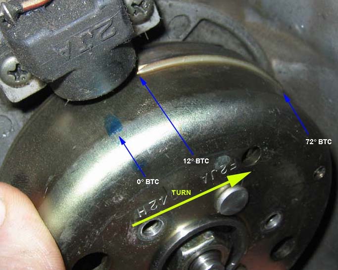
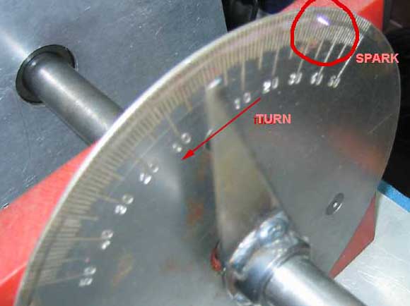
IGNITION TEST MACHINE
Here you can see the exact point where the spark is done while the arrow turns at high speed
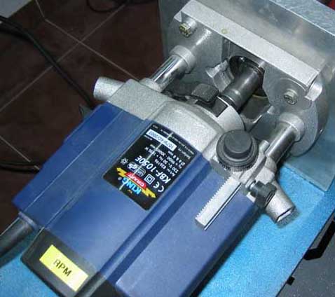
This electric motor can reach upto 30.000 rpm. When the electric motor moves the machine,
the alternator generates the power for the ignition performing. No external power is required.
Download files
CDI Ignition (high-voltage Capacitor Discharge Ignition)
C source code: ignition.c (CCS compiler)
ASM source code: ignition16.asm (MPLAB assembler)
TCI Ignition (12-Volt Transistor Ignition)
C source code: ignition_TCI_PIC12F675.c (CCS compiler)
ASM source code: TCI12F675.asm (MPLAB assembler)
Ignition Wizard" program: SPIgnition.zip
Excel sheet with calulated values: ignition.xls
Other links
NEW! Assembled ignition/EFI kit: It includes a powerful PIC18F6627 microcontroller at 40 mhz, and it is provided with the IGNITION firmware loaded (EFI firmware is optional)
DC-DC converter (engines without high volt alternator)
Click here to go to the servo's page
Last modified: SEP/28/2009